China Top 10 Tips for Better CNC Aluminium Surface Finish?

Time:2026-10-09 Author:Madeline
0%

Achieving a clean, consistent aluminium surface requires more than choosing a sharp cutter. Tool geometry, spindle speed, feed rate, coolant, workholding, and alloy condition all influence the final result. Even a small vibration can leave visible waves across a machined pocket. That detail matters.

So, how can manufacturers answer the practical question, “How to improve surface finish in CNC aluminium parts?” The answer begins with process control, not polishing alone. Aluminium can smear, build up on the cutting edge, or develop burrs when heat and chip evacuation are poorly managed. A suitable carbide tool, polished flute, stable fixture, and controlled coolant flow can prevent many of these defects before they appear.

Dr. Steven Y. Liang, a respected machining researcher, has emphasized, “Machining performance depends on understanding the interaction between the tool, workpiece, and process.” This principle supports every recommendation in this guide. Surface finish is not an isolated machine setting. It is the visible outcome of several connected decisions.

Small changes help.

However, no setup is perfect. A feed rate that works beautifully on one 6061-T6 component may produce chatter on a thinner part. Tool wear may also remain unnoticed until the third or fourth batch. That is why experienced teams inspect tool edges, measure roughness, and compare actual results with drawing requirements.

The following ten tips examine practical ways to improve CNC aluminium finishing. They focus on measurable adjustments, realistic shop-floor conditions, and mistakes that are easy to overlook. Expect useful guidance, but also test each recommendation against your machine, alloy, tooling, and production goals.
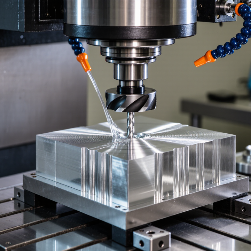
China Top 10 Tips for Better CNC Aluminium Surface Finish?

Choose 6061-T6 or 7075-T6 Aluminium for Consistent Machining Results

Choosing the right aluminium alloy strongly affects CNC surface finish. In practical machining, 6061-T6 is often the safer starting point. It cuts smoothly, forms manageable chips, and offers reliable corrosion resistance. Its balanced hardness also reduces sudden burr formation around pockets and drilled holes.

7075-T6 provides higher strength and stiffness. It can produce a clean finish when the machine is rigid and cutting tools remain sharp. However, its higher strength may increase cutting pressure and tool wear. Its corrosion resistance is also lower than 6061-T6. That difference matters for exposed parts or components receiving anodizing.

Small details still control the final appearance. Use polished carbide tools, steady coolant flow, and suitable chip clearance. Avoid rubbing with worn tools. A moderate radial engagement can reduce heat and visible tool marks. I once blamed the alloy for a rough wall, but the real issue was poor workholding. That assumption was too simple. Test both alloys with the same spindle speed, feed rate, tool geometry, and finishing pass. Measure roughness instead of judging it only under workshop lighting. 6061-T6 usually offers more forgiving results, while 7075-T6 rewards tighter process control. Surface finish can vary between suppliers, even under the same T6 designation. Review the material certificate and inspect the actual batch before committing to production.

Use Sharp 2–3-Flute Carbide Cutters with a 15–30° Helix Angle

Sharp 2–3-flute carbide cutters are a practical starting point for aluminium surface finishing. Fewer flutes create wider chip channels and reduce chip recutting. A 15–30° helix angle also balances cutting smoothness with edge strength. Use a polished rake face when possible. It helps aluminium chips slide away instead of welding to the tool. The International Aluminium Institute’s 2024 industry data shows wide aluminium production across varied alloy families. That matters because 6061, 7075, and cast alloys can behave very differently during cutting.

Keep the cutting edge genuinely sharp. A tiny burr can leave bright streaks across a flat pocket. Start with manufacturer-tested cutting data, then adjust feed per tooth after checking chips and sound. Aluminium often prefers high spindle speed, but heat still damages the finish. In practical trials, a moderate 15–30° helix can reduce vibration on thin walls, though a higher helix may cut more quietly in some machines. It is not a universal rule. The CIRP machining literature repeatedly links stable chip evacuation and controlled engagement with lower roughness. Measure the result using ISO 21920-2 surface parameters, rather than judging reflectivity alone. A mirror-like surface can hide torn material. I have also found that excessive radial engagement ruins finish faster than a slightly imperfect feed setting. One mistake remains common: replacing a dull cutter without cleaning built-up aluminium from the holder and workholding area.

Set Aluminium Cutting Speeds at 150–300 m/min and Feed 0.05–0.15 mm/tooth

China Top 10 Tips for Better CNC Aluminium Surface Finish?

Aluminium cutting speeds between 150 and 300 m/min can produce a bright, consistent surface finish. The correct value depends on alloy hardness, cutter diameter, tool geometry, and machine rigidity. For a 10 mm cutter, this range equals roughly 4,775 to 9,550 rpm. Check the machine’s actual spindle limit before selecting a setting.

Use a feed of 0.05–0.15 mm per tooth, then adjust it according to cutter engagement. A three-flute cutter running at 6,000 rpm and 0.08 mm per tooth gives 1,440 mm/min. That calculation is simple. Surface quality is not.

A sharp, polished cutting edge helps prevent built-up material on the tool. Secure workholding also reduces vibration, especially during thin-wall machining. Keep chips away from the cutting zone with suitable air or coolant. Recut chips can leave fine scratches across the aluminium face.

I usually begin near 200 m/min and 0.08 mm per tooth, then inspect the machined surface under strong light. If the finish looks smeared, the tool may be rubbing or loading. If it shows regular waves, vibration or excessive tool overhang may be responsible. These settings are a starting point, not a guarantee. Actual results can change between aluminium grades, even on the same machine. Reducing the feed may improve appearance, but it can also increase rubbing and heat. That trade-off deserves testing.

China Top 10 Tips for Better CNC Aluminium Surface Finish? - Set Aluminium Cutting Speeds at 150–300 m/min and Feed 0.05–0.15 mm/tooth

No. Surface-Finish Tip Recommended Data Practical Setting Reason and Quality Check
1 Set the cutting speed correctly 150–300 m/min for aluminium with carbide tooling For a 10 mm cutter, approximately 4,775–9,550 rpm using n = 1000Vc ÷ πD A suitable surface speed helps limit built-up edge and excessive heat. Confirm the machine spindle limit before applying the calculated rpm.
2 Control feed per tooth 0.05–0.15 mm/tooth for a general aluminium finishing start point For 3 flutes at 6,000 rpm: approximately 900–2,700 mm/min using Vf = n × z × fz Too little feed can cause rubbing; too much feed can increase scallops and deflection. Adjust after checking chip formation and cutter load.
3 Use a sharp, polished carbide cutter 2 or 3 flutes; polished flute surfaces; sharp positive cutting geometry Use a tool designed for non-ferrous metals and reserve worn tools for roughing or replacement. Polished flutes improve chip evacuation and reduce aluminium adhesion. Inspect the edge for a built-up edge, chips, or a dull corner.
4 Maintain low tool runout Preferably ≤0.01 mm measured near the cutting edge Clean the holder, collet, tool shank, and spindle taper before assembly; use balanced toolholding where available. Runout causes uneven tooth loading and visible lines. Measure with a suitable indicator and correct the setup before changing cutting data.
5 Reduce tool overhang Keep the exposed length as short as the workpiece allows; aim for a length-to-diameter ratio below 4:1 when practical Use a shorter tool or a more rigid holder for deep features. Reduce radial engagement if a long reach is unavoidable. Shorter overhang increases rigidity and reduces chatter, deflection, and dimensional taper on finished walls.
6 Use climb milling for the finish pass Climb milling is generally preferred on a rigid CNC machine Leave a consistent finishing allowance, then use one continuous, stable finish pass where possible. Climb milling usually produces a cleaner shearing action and less rubbing. Verify that backlash is controlled before using it.
7 Use an appropriate finishing allowance Typically 0.20–0.50 mm radial stock for a final wall pass, depending on rigidity and part size Keep the allowance uniform; avoid taking a nearly zero cut that only rubs the surface. A consistent chip thickness improves finish stability. Excessive stock increases cutting force and may cause deflection.
8 Control radial engagement and step-over For a light wall finish, approximately 5–15% of cutter diameter radial engagement Use a smaller step-over for curved surfaces when lower scallop height is required. Lower radial engagement reduces cutting pressure and tool deflection. Calculate stepover from the required scallop height on 3D surfaces.
9 Remove chips and manage heat Use air blast, through-tool air, or suitable flood coolant; keep the cutting zone clear Direct airflow or coolant at the tool–work interface, especially in pockets and during high-speed slotting. Recutting aluminium chips can scratch the surface and promote built-up edge. Check that chips are evacuated rather than compacted.
10 Finish with a stable toolpath and deburr carefully Use smooth entry and exit moves; avoid abrupt direction changes; remove burrs with a controlled process Use a lead-in/lead-out where possible and inspect the surface under consistent lighting after deburring. Sudden engagement changes can leave witness marks. Burr removal should not round functional edges or create secondary scratches.

Note: These values are practical starting ranges for CNC aluminium machining. Final settings should be adjusted for aluminium alloy, cutter diameter and geometry, machine rigidity, workholding, tool condition, coolant method, and the required surface-finish specification.

Control Tool Runout Below 0.01 mm with Flood Coolant or MQL Lubrication

A clean aluminium surface begins with controlled tool runout. Keep radial runout below 0.01 mm at the cutting edge. Measure it with a calibrated dial indicator after cleaning the holder, collet, and tool shank. Even a small chip under the collet can create visible lines across a flat wall. Measure it cold.

In practical machining, I check runout at two points along the tool. A difference between them may indicate taper, tool damage, or poor seating. Use a sharp, balanced cutter and avoid excessive tool extension. Shorter tools usually reduce vibration. Reduce the problem at its source.

Flood coolant works well during deeper cuts because it cools the tool and carries aluminium chips away. Aim the nozzle directly at the cutting zone, not merely at the workpiece. Weak flow can leave chips rubbing against the finished surface. Check coolant concentration regularly, since unstable mixtures may reduce lubrication.

MQL lubrication can produce excellent finishes during lighter cuts and high-speed operations. It supplies a small oil mist, reducing built-up edge on the cutting lip. However, MQL does not always remove chips effectively. Air assistance may be necessary, especially inside pockets. I have seen fine finishes fail because chip evacuation was overlooked. Do not trust appearance alone; inspect the surface under angled light and verify roughness with a suitable tester. Personally, I still allow a small finishing allowance because real fixtures are rarely perfect.

Measure Ra Under ISO 21920, Targeting 0.8–3.2 µm Before 5–25 µm Anodizing

For CNC aluminium parts, surface finish is not a visual guess. It is a measured process result. Before anodizing, set a practical Ra target between 0.8 and 3.2 µm. This range often balances machining marks, appearance, and coating consistency. The correct value still depends on geometry, alloy, toolpath, and lighting.

Measure according to ISO 21920 with a calibrated contact instrument and a documented evaluation setup. Select the cutoff and assessment length for the surface texture, not by habit. Record the stylus direction, measurement locations, and calibration status. Check several areas, especially pockets, edges, and broad visible faces. One reading can look reassuring, yet it may hide chatter near a corner. Clean chips and coolant residue first. They distort results.

Anodizing thickness between 5 and 25 µm can emphasize existing lines or change the reflected appearance. It does not reliably erase poor machining. Production reviews often reveal parts that pass visual checks but show directional feed marks after anodizing. That mistake is easy to repeat. Review Ra alongside Rz, waviness, and functional requirements when the surface seals, slides, or needs close cosmetic inspection. Keep a witness sample from each setup and compare it after coating. The comparison may expose an uncomfortable truth: the chosen Ra target was convenient, not suitable.

FAQS

Which aluminium alloy is easier to machine consistently?

6061-T6 is usually the safer starting point. It cuts smoothly and forms manageable chips. Its balanced hardness can reduce burrs around holes and pockets.

When can 7075-T6 produce a better surface finish?

7075-T6 can finish cleanly with rigid workholding and sharp tools. Its higher strength increases cutting pressure and tool wear. It rewards tighter process control.

What Ra range is practical before anodizing?

A practical pre-anodizing target is 0.8–3.2 µm Ra. The exact target depends on geometry, alloy, toolpath, and lighting. Do not treat this range as universal.

How should aluminium surface roughness be measured?

Use a calibrated contact instrument and a documented ISO 21920 setup. Record the cutoff, assessment length, stylus direction, and calibration status. Clean away chips and coolant first. Residue can distort readings.

Can anodizing hide poor machining marks?

Not reliably. A 5–25 µm coating may emphasize feed lines or change reflections. Inspect the machined surface before coating. The finish may look acceptable, then fail under bright light.

Which machining details help reduce visible tool marks?

Use polished carbide tools, steady coolant, and clear chip paths. Avoid rubbing with worn tools. Moderate radial engagement can reduce heat and marks.

Could poor workholding cause a rough wall?

Yes. A rough wall may come from vibration, not the alloy. I once blamed the material too quickly. That assumption was too simple.

How should two aluminium alloys be compared fairly?

Use the same spindle speed, feed rate, tool geometry, and finishing pass. Measure roughness instead of judging parts under workshop lighting. Check pockets, edges, and broad faces. One reading is not enough.

What should be reviewed before production approval?

Review Ra with Rz, waviness, and functional requirements. Inspect the actual material batch and its certificate. Keep a witness sample from each setup. The convenient Ra target may be wrong.

Conclusion

Achieving a consistent CNC aluminium surface finish starts with selecting a stable material, such as 6061-T6 or 7075-T6, which supports predictable cutting performance. Use sharp, polished 2–3-flute carbide cutters with a 15–30° helix angle to reduce built-up edge and improve chip evacuation. Recommended cutting speeds are typically 150–300 m/min, with a feed rate of 0.05–0.15 mm per tooth, adjusted according to the tool, machine, and workpiece conditions. Keeping tool runout below 0.01 mm is also essential for uniform cutting and reduced vibration. Flood coolant or MQL lubrication can further control heat and prevent aluminium from sticking to the tool.

For those asking, “How to improve surface finish in CNC aluminium parts?”, finish quality should be verified through Ra measurement according to ISO 21920. A practical pre-anodizing target is usually 0.8–3.2 µm, while anodizing thickness commonly ranges from 5–25 µm. Careful control of material, tooling, cutting parameters, lubrication, and inspection helps produce reliable, attractive results.

Madeline

Madeline

Madeline is a dedicated marketing professional with a wealth of expertise in our company's core offerings. With a keen understanding of the industry, she brings a unique perspective to her role, consistently delivering high-quality content that highlights the superior aspects of our products. As......